
Support center
Provide you with comprehensive product operation guidelines
Installer
To ensure that your inverter can be smoothly integrated into the HEMS system, it is recommended to follow the steps below:
Step 1 – Confirm the connection method and interface parameters of the inverter to the HEMS system
- Modbus-RTU communication has been established between the HEMS Controller and most models of Solis Inverters. You can use RS485 wiring to connect the two devices.
- Refer to the Solis Inverter User Manual to confirm the exact location of the RS485 interface, as well as the factory default parameters and the method for modifying them.
Step 2 – Establish the correct connection between the inverter and the HEMS Controller
- Based on the RS485 interface parameters of the Solis Inverter, connect the RS485 cable to the corresponding RS485 interface of the HEMS Controller.
(The interface parameters and configuration method for the HEMS Controller can be found in the detailed examples below or in the User Manual and other materials.)
Step 3 – Enter interface parameters in the enjoyelec app
- After completing the wiring, power on the devices. Open the enjoyelec app to bind the device and enter the interface parameters that match the actual setup.
(For detailed instructions on configuring the app, please refer to the User Manual.) - Once the configuration is complete, the Solis Inverter will be integrated into the HEMS system, allowing you to perform functions such as querying and controlling the device via the app.
Example
The following provides a detailed explanation of the process for integrating the inverter into the HEMS system, using the GOODWE Inverter model GW3000-XS as an example:
Step 1 – Confirm the connection method and interface parameters of the inverter to the HEMS system
GW3000-XS:

- The communication interface of the GOODWE Inverter is located at the bottom of the device. By consulting the Inverter’s User Manual, you can find that the Communication interface (COM) is located as follows:

| No | Parts | Description |
|---|---|---|
| 1 | DC Switch(optional) | Optional. During normal operation it is in “on” state,it can shut down the inverter after it is disconnectedfrom the grid by the Ac breaker.For Australia and New Zealand: With DC Switch. |
| 2 | PV Input Terminal | Used to connect the PV module DCinput cables |
| 3 | WiFi/LAN/4G CommunicatiorModule Port |
|
| 4 | RS485/DRED/CT/RemoteShutdown CommunicationCable Port(optional) | Optional. Used to connect the RS485, DRED, CT, OrRemote Shutdown communication cable. |
| 5 | AC Output Terminal | Used to connect the Ac output cable, which connectsthe inverter and the utility grid. |
| 6 | PE Terminal | Used to connect the PE cable. |
| 7 | Indicator | Indicates working state of the inverter. |
| 8 | LCD | Used to check the parameters of the inverter |
| 9 | Button | Used to select menus displayed on the screen |
| 10 | Heat Sink | Used to Cool the inverter. |
| 11 | Mounting Plate | Used to install the inverter |
- According to the user manual, the COM port marked as “4” is used for RS485 communication. The pinout of the COM connector is shown in the diagram below:

- The baud rate of the RS485 port on the GOODWE Inverter is typically set to 9600 by default.
If you need to verify or modify relevant parameters, you can use the GOODWE Inverter app to scan the QR code near the inverter, connect to the inverter, and enter the app’s configuration page to view or make changes.
Step 2 – Establish the correct connection between the inverter and the HEMS Controller
When connecting the inverter to the HEMS Controller via RS485, it is essential to ensure that the port parameters of both devices match. The port location for the controller with a baud rate of 9600 is shown in the diagram:
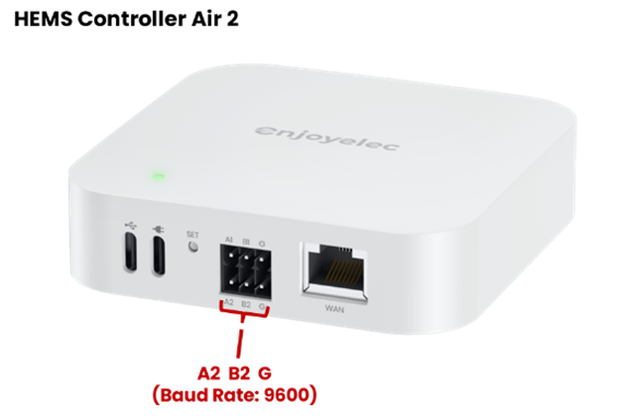
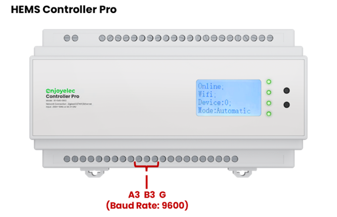
(For selecting a different baud rate, please refer to the user manual for verification.)
- When wiring, please pay attention to the color differentiation of the A and B cables to ensure that the port wiring sequence on the Controller side correctly matches the port sequence on the Inverter side.
- If a different baud rate port is required, you can refer to the User Manual to locate the corresponding port, or use the enjoyelec App to set the port parameters on the Controller.
Step 3 – Enter interface parameters in the enjoyelec App
After completing the physical connection between the Inverter and the Controller, the relevant parameters need to be configured in the Enjoyelec app:
- In the app, select the device type, brand, and model of the device connected to the Controller.
- Configure the communication method between the Controller and the Inverter in the app, including the communication protocol, physical port number, port parameters, etc.
- Once the parameter configuration is complete, send the configuration information to the Controller. The Controller and the sub-device will begin pairing and establishing a connection, enabling data collection and control of the sub-device.
 Dutch
Dutch English
 Finnish
 French
 German
 Italian
 Norwegian
 Portuguese
 Spanish
 Swedish